AO System Calibration
Introduction
Before the AO system can be used for real-time control of wavefronts, it must be calibrated. There are several aspects of the calibration process.
Preparatory calibrations include:
- Measuring the DM modal response functions
- Determining the illuminated subapertures
- Registering the DMs to the wavefront sensor
- Determining the pupil footprint on each DM
- Measuring the Hartmann slopes response to DM modes
- Calculating the nominal control matrix
Operational calibrations include:
- Measuring the camera backgrounds
- Determining the reference centroids (including the process of image sharpening)
ToDo Similar sets for the Tip/Tilt sensor. For example, determining the field rotation angle
Pupil Registration
This image shows the woofer actuator map and anticipated pupil footprint:
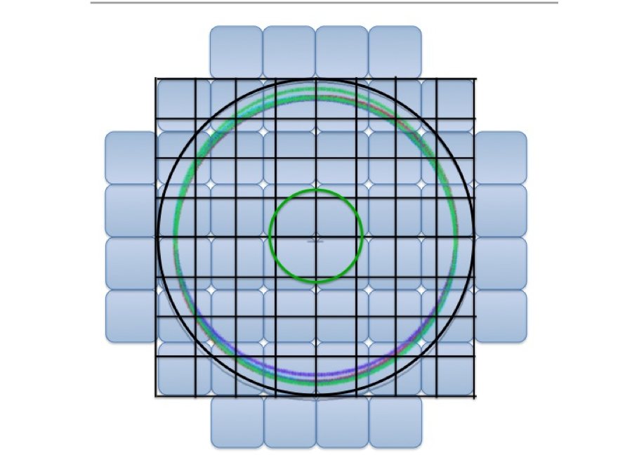
Figure 1 Woofer actuator layout (blue pads), with overlie of the 8x8 lenslet geometry (black squares)
The following two images show the tweeter actuator layout, the anticipated pupil footprint, and the Hartmann lenslet geometry for 8x and 16x modes:
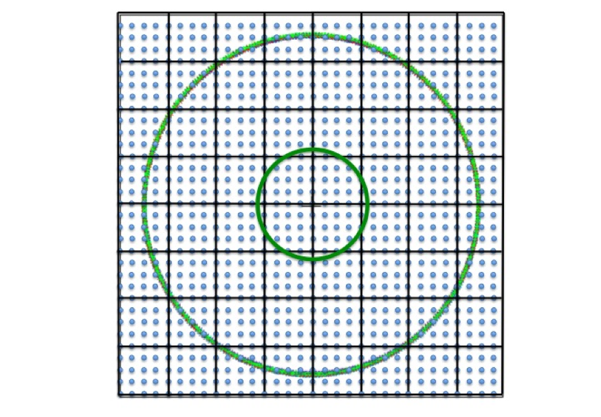
Figure 2 8x8 lenslet geometry (black squares) on the tweeter actuator grid (blue dots)
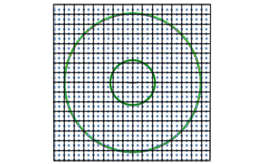
Figure 3 16x16 lenslet geometry (black squares) on the tweeter actuator grid (blue dots)
DM Pokes
It is possible to put patterns or modes on either of the DMs.
If you want to do this independently of the real-time code (for example, move only the DM, but use the engineering GUI for the wavefront sensor), then start python and enter:
import pattern
See DM Pattern Generator for a description of the commands and available patterns.
Patterns can also be put on the DMs when running the real-time code. First, open the control loop, then set the integrator bleeds to all ones. This will freeze any pattern you subsequently load in to the integrators:
flat()
bleed(1)
tweeter_poke(pattern)
woofer_poke(pattern)
See more details about these commands and the available patterns in the documentation for Top Level Command Processor shaneao.
Calculating the Control Matrix
The DM response functions have been characterized in the laboratory (raw data are stored in the documentation archive). These data are used to calculate various intermediate matrices that lead ultimately to the generation of the control matrix:
| Module | Matrices Calculated |
|---|---|
| sauce | At Aw Mt Mw Cwt |
| calibrate | H |
| param_gen | controlMatrix |
These matrix sets depend on the WFS mode. The matrices are stored in ~/parameterFiles/reconMatrix_{mode} where mode is ‘8x’ or ‘16x’.
If you need to do recalibrations, you first need to know that the geometries are defined in the sauce simulator. Once satisfied these accurately describe the system, you can run some or all of the scripts to regenerate the matrices.
To calculate At, Aw, Mt, Mw, and Cwt, start python and execute:
import sauce
sauce.init()
sauce.save()
This will save files in the ~/parameterFiles directory. Before overwriting the old ones, it will attempt to protect them by copying them to an archive subdirectory with a time stamp appended to the file name.
To calculate H, which is the forward matrix mapping modes on the tweeter to wfs centroid signatures, you need to run ShaneAO in simulate mode, (on a computer other than rtc). Do this by typing shaneao at the unix prompt. Then:
import calibrate
calibrate.calibrate()
This process will save the H matrix, again protecting the old file in an archive.
ToDo Eventually there will be a similar process using the real rtc and WFS centroid data to generate the forward matrix.
Finally, to calculate the control matrix, start python and execute:
import param_gen
param_gen.gen_CM(mode)
where mode is the string ‘8x’ or ‘16x’.
Operational Calibrations
Operational calibrations are usually done just before an observation or while experimenting in the laboratory. They can also be done in the simulator.
Start the Top Level Command Processor for the AO system by typing shaneao at the unix prompt.
Camera Backgrounds
To record a camera background, point the telescope to a blank section of sky with no starlight entering the wavefront sensor, and execute:
dark()  # take a wfs dark frame
ttdark() # take a tip/tilt sensor dark frame